
Ok I know these are rarer than gold dust and I am watching the usual places but if anyone see's one anywhere or has one let me know.
Cheers
Martin
Cheers
Martin
Martin

A social community of enthusiasts, owners, appreciators and collectors. With expert knowledge of all things from MG to Rover and beyond.

Merl wrote:Ok I know these are rarer than gold dust and I am watching the usual places but if anyone see's one anywhere or has one let me know.
Cheers
Martin

Merl wrote:Paul would this be something you could check at the nanomeet? or is it quite obvious to tell?
Merl wrote:Ok cool thankswill have to be the next one though as at MG meet in Belgium for this one
Merl wrote:ahh so SW20 then is the switch point, doh it's like looking at a remote or computer keyboard with the points, as long as there is that extra point there then its ok.
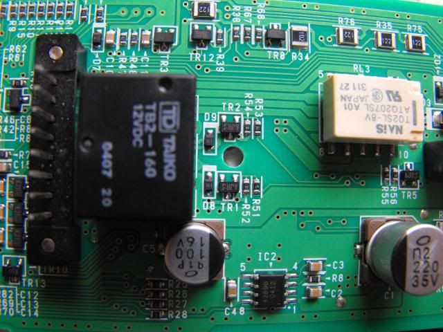
JohnDotCom wrote:There is also at least four additional Transistors and a few Diodes and Resistors and other components (TR13) for one, required to make it all work.
JohnDotCom wrote:There is also at least four additional Transistors and a few Diodes and Resistors and other components (TR13) for one, required to make it all work.