Yup, you read it right, Now fitted the prototype to my car to see how it stands up to normal life. 
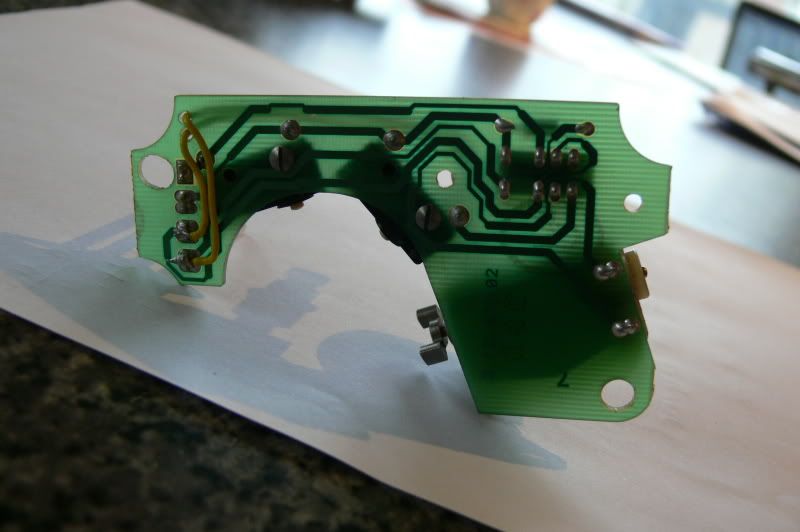
Here you can see a standard Power VIS (Variable Intake System) pcb I have prepared for a standard motor, you can see clearly where I screw the ever so troublesome switches to the pcb. Now, the two yellow wires you can see are the ones added for the self test. I have drilled the pcb to allow the two wires to be taken to the other side of the pcb without disturbing it's seating.
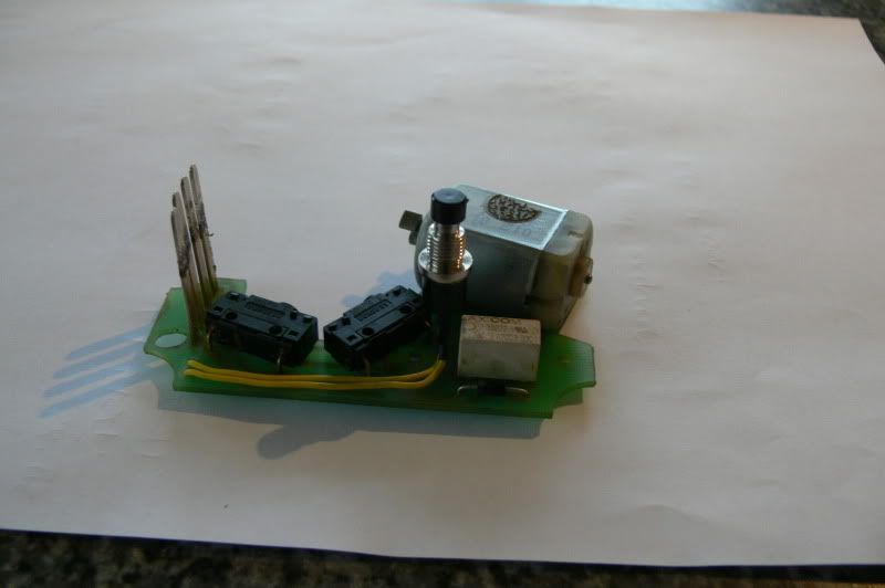
Turning the pcb over you can see there is no need for nuts on the other end of the machine screws as the switches themselfes are tapped. You can also see the test switch fitted, the switch is just short enough to sit next to the relay, heat shrunk the soldered joints just for good measure.
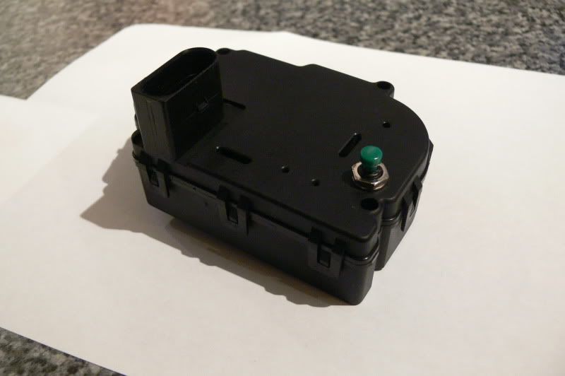
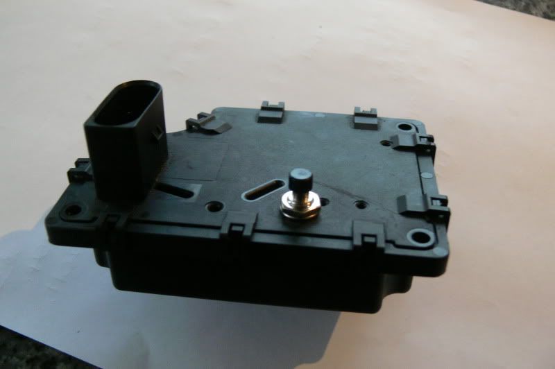
With the top fitted and the lock nut fitted to the switch it fits together absolutely as normal. I have used black heat resistant silicone on the underside of the switch to seal it to the casing top.
all that is left to do is to road test it for a while.
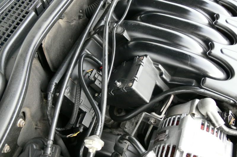
Operation couldn't be simpler, turn ign on but do not start car. Press the button on the VIS motor and hold, you can hear the VIS motor across, release the button and you will hear the motor return
The test button is a "push to make momentary" and remains active for a couple of mins after ign off as the motors are powered until the car goes to sleep
Here you can see a standard Power VIS (Variable Intake System) pcb I have prepared for a standard motor, you can see clearly where I screw the ever so troublesome switches to the pcb. Now, the two yellow wires you can see are the ones added for the self test. I have drilled the pcb to allow the two wires to be taken to the other side of the pcb without disturbing it's seating.
Turning the pcb over you can see there is no need for nuts on the other end of the machine screws as the switches themselfes are tapped. You can also see the test switch fitted, the switch is just short enough to sit next to the relay, heat shrunk the soldered joints just for good measure.
With the top fitted and the lock nut fitted to the switch it fits together absolutely as normal. I have used black heat resistant silicone on the underside of the switch to seal it to the casing top.
all that is left to do is to road test it for a while.
Operation couldn't be simpler, turn ign on but do not start car. Press the button on the VIS motor and hold, you can hear the VIS motor across, release the button and you will hear the motor return
The test button is a "push to make momentary" and remains active for a couple of mins after ign off as the motors are powered until the car goes to sleep
Photobucket = Tossers
Dave....
Dave....